Camshaft Selection -- by Michael
Ecker
I am by no means an expert, but have
done extensive research into cams - the relationships between lift &
duration & lobe centers and power.
For a given duration, the cam that
produces the highest lift will produce the most power with very little effect
on driveability. Driveability is
chiefly a matter of duration and overlap, and overlap is a direct function of
lobe center angle as well as duration. Obviously, if the centers of the lobes
are kept at a constant separation and the duration is increased, the lobe
widens to both sides of the center. Therefore 1/2 of the intake duration
increase and 1/2 of the exhaust duration increase add directly into the
overlap.
Overlap is the time period when both
the exhaust valve (trying to close) and the intake valve (starting to open) are
open at the same time. The exhaust
valve needs to stay open after the piston passes Top Dead Center in order to
use the momentum of the exiting exhaust gases to maximize the amount of exhaust
gas pulled out of the cylinder. The
intake valve opens before Top Dead Center in order to use the momentum of the
exiting exhaust gas to start pulling the intake charge into the cylinder. Too large of a lobe center angle can result
in too little overlap to make good power.
Too little overlap causes two things: lack of full expulsion of the
exhaust gases and less intake charge filling the cylinder. Smaller amounts of overlap produce a
smoother idle and a slight benefit in top end horsepower. This effect of overlap on performance is
directly linked to RPM, as higher engine speed causes greater exhaust gas
velocity, which relates to greater momentum of the exiting exhaust gases. This is one of the reasons that a longer
duration cam produces power higher in the RPM range - the overlap period is
longer requiring higher exhaust gas velocity for this momentum effect to occur
without allowing excessive amounts of exhaust gases to enter the intake tract
or to allow the exiting exhaust gases to pull the fresh intake charge right
through the cylinder and into the exhaust system. Both of these events cause the loss of bottom end power and
economy that large cams experience, however at higher engine speeds these are
minimized due to the slight lag time it takes to get the intake charge moving
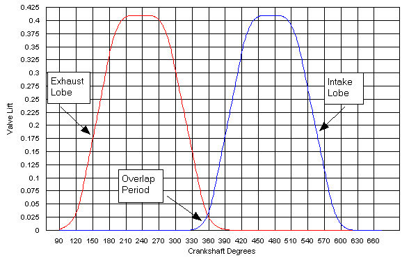
into the cylinder. The following
diagrams illustrate plots of valve lift vs crankshaft angle, and shows the
overlap period. (We will discuss the difference between these two diagrams a
little later.)
The second point in the cam timing
which we will discuss, and which has an equally great effect on the RPM range
of a cam, is the intake valve closing.
The intake charge also develops a certain amount of momentum while it is
filling the cylinder. This is why the
intake valve does not close until after Bottom Dead Center, to allow this
momentum to maximize the filling of the cylinder. There are two things that conflict here - the piston is starting
to move upwards while the fuel/air charge is still flowing into the cylinder
due to momentum. The momentum decreases
as the pressure from the rising piston increases. At some point the cylinder pressure overcomes the momentum and
will start pushing the mixture back into the intake manifold if the intake
valve is still open (this is called reversion). This is directly linked to engine RPM as higher engine speeds
cause greater momentum in the intake charge.
A small cam will produce very little reversion, but will restrict
cylinder filling at higher engine speeds because the mixture is still rushing
into the cylinder when the intake valve closes and stops the flow. A longer duration cam will allow the engine
to use the intake charge momentum more fully at higher engine speeds, but at
the cost of high amounts of reversion at low RPMs (which causes poor low end
power and rough idling).Keep in mind that as you increase the intake duration,
you need to increase the exhaust duration comparably to balance out the system. You want enough exhaust opening to purge the
gases that the intake allows the cylinder to ingest at a given RPM.
Back to lobe centers - tests have
shown that, for a given cam profile, a smaller lobe center angle will produce
more average power and a quicker revving engine. This is at the expense of a small amount of bottom end and idle
quality due to the slightly increased overlap.
In reality, a cam with 220º at 0.050" and a lobe center angle of
112º will have the exact same mechanical overlap as a cam with 217º at
0.050" and a lobe center angle of 109º.
If you compared these two cams side by side in identical engines, the
first cam would actually have a slightly better idle and would probably produce
slightly more peak power at upper RPMs, but the second would produce more
torque in the 2000-5000 range and would rev quicker. My experience has been that lobe centers of 109º-110º work very
well in Olds engines, and have gone as low as 107º in a high performance Olds
350 that I built with very strong results (it was a street car that would eat
BBC cars for lunch). Now go back and
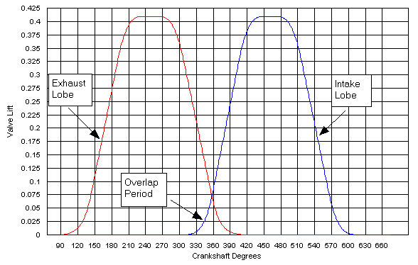
look at the first two diagrams. The
first shows a cam with a very wide (118 degrees) lobe center angle, while the
second has a very narrow (106 degrees) lobe center. It should be noted that lobe center angles are measured in
camshaft degrees (which is 1/2 of the equivalent crankshaft angle.) The first cam would have a very smooth idle
but would give up considerable mid-range power and would seem a little lazy on
acceleration. The second cam would have
a much rougher idle, but would pull much harder through the mid-range RPM's.
This leads is into a related topic -
the relationship between cam duration and engine vacuum. First, with a longer duration cam you have
more overlap (the period when both the intake and exhaust valves are
open). The intake valve is opening
sooner when the pressure in the cylinder is still high. This causes some of the exhaust gas to push
back into the intake port (reversion).
This is then drawn back into the cylinder with the fresh intake charge
as the momentum of the exhaust gas exiting through the exhaust valve creates a
vacuum in the cylinder and begins drawing the intake charge into teh
cylinder. The net effect is to decrease
the amount of intake charge that is drawn in slightly due to the exhaust gas
contamination in the intake tract (similar effect to an EGR valve which is
stuck open).
Secondly, the intake valve is staying
open longer. All cams keep the intake
valve open until after the piston has passed Bottom Dead Center and begun to
move back up in the cylinder to take advantage of the momentum of the fuel/air
mixture that is entering the cylinder.
At some point, the pressure which is building in the cylinder from the
piston coming back up overrides the momentum of the mixture which is entering
the cylinder. Maximum cylinder filling
and measured compression will occur if the intake valve closes just as this
point is reached. The problem here is
that as engine speed increases there is an increase in the momentum of the
incoming mixture, which therefore needs a later intake valve closing to reach
the balance point and maximize cylinder filling.
Unfortunately with a performance cam
this places the intake closing after the ideal point for low RPM operation. This results in some of the intake charge
being pushed back out into the intake manifold due to the rising cylinder
pressure from the rising piston. Since
vacuum is directly related to the actual amount of air being drawn into an
engine per cycle, anything which keeps the engine from pulling fresh air/fuel
mixture into the cylinder and KEEPING it there will cause a decrease in engine
vacuum. By the same token, this is why
a larger engine will develop more vacuum with a given cam than a smaller one -
all else being equal the larger engine is still pulling more air through it per
engine cycle at a given RPM, even if the cam is not very efficient at that
RPM. This is also why advancing a cam
by 2-5 degrees is common. This allows
the intake valve to close a little earlier than if the cam were installed
"straight up" (this means the intake lobe center and exhaust lobe
center ar the same distance from top dead center), which in turn makes the cam
act like it is has a few degrees less duration than it really does without
actually shortening the amount of time the engine can breathe through the open
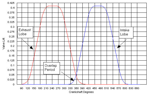
valves. For an example see the
following diagrams. The first shows a
dual pattern cam (longer exhaust duration than intake) with the lobe centers
equally spaced from Top Dead Center.
The second diagram shows the same cam installed five degrees
advanced. The difference does not look
very large, but the difference in the RPM where peak power is produced can vary
by several hundred RPM and the difference in idle quality and low end power
would definitely be noticeable.

If you think about it, this also
explains the limitations of a stock or near stock cam. With a shorter exhaust duration to allow the
gases to escape and an earlier intake closing which stops the fuel/air mixture
which is trying to enter the cylinder at higher RPM and a wide lobe center
angle, the engine reaches optimal running conditions around 2000-2500 RPM but
quickly runs out of breath above about 4500-5000 RPM.
Last important topic: the elusive
"area under the curve". For
those of you that have not heard this term before, this refers to a plot of the
valve lift against the crankshaft angle.
Most articles on camshaft design show a diagram of this - it looks like
two bell curves which overlap (hence the term) in the middle. Now consider two cams with the same duration
at 0.050" valve lift. (By the way, this figure is the most valuable in
terms of comparing cams because this is the point when actual flow past the
valve really begins.) The advertised,
or gross, duration of the cam is usually measured from the point of 0.004"
valve lift. The smaller the difference
between these two numbers, the steeper or more aggressive the lobe profile
is. Cams with a smaller difference
between these two will have a larger maximum valve lift (unless the cam is
specifically designed to max out at a lower lift) because the valve lift is
increasing more per degree of rotation (this assumes the cams have the same
0.050" duration). If you increase
the maximum lift by 10%, you significantly increase the area under the curve of
valve lift vs. crankshaft angle.
Consider this curve as the window that the engine can breathe
through. Increasing this window by 5%
by using a larger lift and more aggressive profile has the same effect as using
a longer duration or increasing the valve size - it increases the total window
through which the engine can breathe. The advantage of higher lift instead of
duration is that the higher lift cam will have virtually no effect on idle
quality and low end power. The major
down side to more aggressive cam profiles is the risk of valve float due to
higher valve speeds, which creates more momentum in the valve itself. With good valve-train components (springs,
pushrods, etc.), and assuming a reasonable RPM limit, this is not a major
consideration.
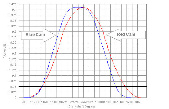
Now, take a minute to look at the
following picture. The blue curve
represents a fairly aggresive lobe profile which is designed to adhere to a
0.410" lift limitation (as is common in many racing classes). This is why the top of the lobe is kind of
flattened out. The relatively short
duration of this cam would suggest a short (around ¼ mile) paved oval
track. The red curve, however, is a
less aggressive curve with a longer duration.
The area under the curves (only considering above 0.050" valve lift
as this is where flow starts) is very comparable here. The big difference is in the way these two
cams would act. The blue cam has a gross
duration of 255 degrees and a 0.050 duration of 204. The red cam has a gross duration of 280 and a 0.050 duration of
230. Quite a large difference in specs,
but they would have very similar mid-range power curves. The blue cam would idle much better and
respond stronger up to about 2500 RPM, but would drop off above about 5000
RPM. The red cam would be much less
responsive below about 3000 RPM, but would really keep pulling strong up to
6000-6500 RPM. From 2500-5000 RPM, they
would be neck and neck. The main reason
the red cam would pull better at higher RPM, as well as the lack of low end for
this cam, gets back to the overlap problem.
The red cam (assuming the same lobe center separation angle) would have
25 degrees more overlap than the blue cam, and an intake closing event which is
12-13 degrees later.
I feel that it is warranted to
mention a couple of other topics since I am pushing the advantages of more
aggressive cam profiles. For flat
bottom lifters (solid or hydraulic) a larger diameter lifter can handle a more
aggressive cam lobe than a smaller lifter.
Again, there is a compromise here because the larger diameter lifter
will tend to have more mass, and therefore develop more momentun at higher
RPM's and produce more stress on the valve springs and a greater risk of valve
float. The flip side of this is that,
assuming a cam company which actively uses the lifter diameter in designing
their cams, a more aggressive and powerful cam can be ground for an engine with
larger lifters (meaning the cam would be able to produce more lift for a given
duration). The reason is that as the
cam turns and the lifter starts to ride up on the opening ramp of the lobe, the
contact point between the cam and the lobe moves towards the edge of the
lifter. The more aggressive the lobe,
the farther the contact point moves.
The contact point cannot ever reach the very edge of the lifter, or
rapid and extreme wear would result and would round off the bottom of the
lifter and wear out the lobe.
This is why a larger diameter lifter
is better - the lobe can be more aggressive because the contact point has more
room to move away from center without running off the edge of the lifter. There are still a few companies which use
this to advantage (I believe Engle cams is one). Chrysler owners have used this advantage in the past (their
lifters are 0.904" diameter) in racing classes requiring flat-tappet cams. Interestingly, the Olds engines with the
larger 0.921" lifters (including the majority of the 350 diesel blocks)
would have a distinct advantage over the competition with a properly ground
cam. To see an example of the benefits
of a more aggressive cam profile, look at the next diagram.
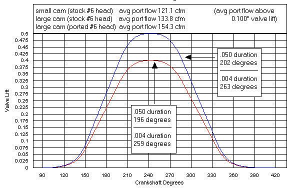
The diagram shows two cams with very
similar gross and 0.050" lift duration figures, however one has a
0.400" maximum lift (like the stock Olds cams) while the other has a
0.500" maximum lift. These cams
have a very conservative duration (the bone stock Olds V-8 cam only has 250
degrees gross intake duration and 264 degrees exhaust duration.) Notice the huge difference in area under the
two curves. Also notice the flow
figures - these were computed using average flow rates for a bone stock #6 head
(using the premise that the flow of these heads maxes out around 0.400"
lift) as well as reasonable flow rates for a ported #6 head with larger valves
where flow peaks above 0.500" lift. Notice that even with a stock head and
with capping flow at 0.400" lift, the larger cam still flows 10% more than
the smaller one above 0.100" valve lift (below this there is no
appreciable difference). With a good
flowing head the larger cam flows a whopping 27% more than the smaller cam. The two cams would have very similar low-end
power and idle quality due to the short duration but the larger lift cam would
show big power increases in the mid-range RPM's (up to the point where the
short duration limits high-RPM power production.)
Another question which frequently
comes up is what rocker arm ratio should be used for a given engine
combination. In general, a larger
rocker arm ratio will produce faster valve opening and increase the amount of
valve lift. Normally this is not a
large difference but larger ratio rockers will produce more power. Look at the following diagram:

Olds engines come stock with 1.6:1
ratio rocker arms, but it is possible to find aftermarket 1.7:1 ratio arms
which can be used with these engines.
As the diagram illustrates the larger arms mainly benefit breathing near
the cam's maximum lift, and will not produce nearly the benefit of going to a
more aggressive cam as can be seen by comparing the area under the two
preceding diagrams. If considering a
change to larger ratio rockers, you need to be aware of some potential
problems. The most obvious are related
to the additional lift - you need to make sure you have adequate piston to
valve clearance, and that there is adequate clearance at full lift between the
bottom of the valve spring retainer and the top of the valve guide. Another consideration is the springs
themselves - there must be proper clearance between the coils at maximum lift
to prevent coil bind, and the spring must be strong enough to prevent valve
float. This is more of a concern with a
higher ratio rocker arm because the valve acceleration and peak speeds are
increased which will make the engine more prone to float the valves. The geometry of the valvetrain must be
verified - the rocker arm tip must be centered over the valve stem at 50% of
maximum lift (especially critical with roller-tip rockers). One final area to check is the
pushrods. Geometry problems can
sometimes be addressed by purchasing custom length pushrods as long as an
adjustable valve train has been installed.
You must also verify that the pushrods have proper clearance where they
pass through the cylinder head (this should be checked through the full range
of motion of the valve.) Higher ratio
rockers move the pushrod cup closer the central pivot which can cause clearance
problems here which result in high wear on the sides of the pushrod and
possibly catastrophic valvetrain failure.
One final topic which I will touch
upon is the various types of hydraulic lifters available (I will confine this
discussion to hydraulic lifters because these are used in the vast majority of
street engines, aside from the OEM roller cam setups which have quite decent
lifters from the factory.) A hydrailic
lifters is a small hydraulic cylinder which uses a small quantity of oil under
a central piston to support the pushrod.
The basic or stock replacement hydraulic lifter is generally quite
satisfactory up to about 5500 RPM. Note
that there are two major types of stock-replacement hydraulic lifters. Both have an internal check valve to control
the oil inside them, but one type uses a check valve with a small metal ball
while the other uses a circular disc to control the oil. Reports indicate that the disc type lifters
are good for about an additional 500 RPM
as compared to the ball style (the ball style lifters were used by most
OEM manufacturers.) Proper operation of
these lifters requires a pre-load (the amount the central piston is depressed
into the pushrod body) of 0.030"-0.050" with the valve fully closed
and the rocker arm properly adjusted (or tightened in the case of the stock,
non-adjustable rockers.)
When performance demands require
better lifters there are two main categories.
One is the "anti-pump-up" or "high-rev" style
lifters. These generally use an
internal snap ring to restrict the movement of the pushrod cup within the
lifter body and are usually good up to 7000 RPM. The down side of these lifters is that pre-load MUST be set in
the range of 0.000"-0.004" (depending upon the particular
manufacturer) - failure to set the pre-load properly will result in rapid
lifter failure. An adjustable valve
train is a MUST with these lifters.
The final class of lifters are the
"variable durarion" style lifters.
These have been marketed by several companies for many years and have
met with mixed success. The theory
behind these is that they allow a controlled leakage of the oil inside the
lifter body, which allows the piston upon which the pushrod rides to slowly
depress as the lifter is rising. This
decreases the "effective" maximum lift and duration of the cam as
seen at the valve. The effect decreases
with engine RPM as there is less time for the lifters to "bleed
down". The largest benefit of
these lifters is an increase in idle vacuum (as much as 2+ inches of extra
vacuum) and low-end response and power (they can make a cam seem to be 10+
degrees smaller than it actually is at lower RPM's) but some of these lifters
have been tested to decrease power at the upper RPM levels as well. Pre-load with these lifters varies by
manufacturer, but is generally around 1/2 turn of the adjusting nut beyond the
zero lash position. I strongly urge
anyone considering these lifters to carefully research the available options
before making a purchase. These lifters
can be useful in the right application but are not a substitute for having a
properly sized cam installed. These
lifters can also be quite noisy due to the lifter's piston contacting the
bottom of the bore in the lifter body.
As a final note regarding these lifters, consider the following quote
from the Comp Cams catalog regarding their variety of variable duration liters:
"This lifter has a greater bleed
rate which greatly increases vacuum, throttle response, and noise. It is designed primarily for extremely hot
street machines or racing applications where a vacuum rule is in place or where
you must run a hydraulic cam. This lifter should not be run for extended
periods on the street."